How Does It Work?
The WSB24 is actually a pretty simple box as the block diagram in Figure 1 shows.
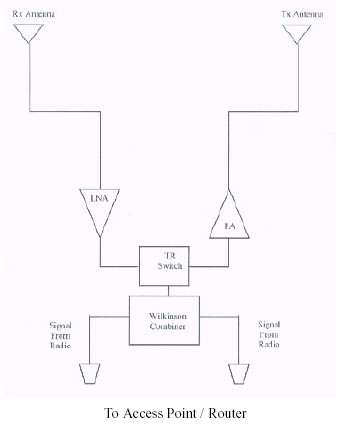
Figure 1: WSB24 Block Diagram
This excerpt from the FCCID filing's detail documents shows that the WSB24 contains a low-noise receive pre-amplifier, transmit power amplifier, Transmit / Receive switch, and signal combiner. That may be hard to follow if you're a little low on the geekometer, so I'll break it down a little bit:
- The combiner takes the two signal inputs from the product that the WSB24 is used with and comes up with a single signal. This is necessary because there is only one transmit and one receive amplifier in the WSB24
- The switch senses whether the product being boosted is transmitting or receiving and automatically switches in the appropriate amplifier.
- And, of course, the amplifiers are what actually provide the signal "boost"
Note that this means that if the product that you're using the WSB24 with has a diversity antenna feature, you lose that function when you add the WSB24. Although the WSB24 has two antennas, Figure 1 shows that one is dedicated to transmitting and the other to receive. I wouldn't worry about the loss, however, since the increased signal strength from the WSB24 should more than make up for the loss of the diversity function.
So how much do those amplifiers actually boost the signal? The FCCID document says that the WSB24 provides a "maximum fixed gain of 10dBm" (although they probably meant 10dB). At any rate, this means the WSB24 should improve both transmit and receive signal power by 10X, which I did confirm as part of my performance measurements.
Note that this does not mean that the WSB24 will increase your Access Point or wireless Router's range by 10X! You will get a performance boost from the WSB24, but what you actually get is definitely a "your mileage may vary" story, as we'll see later in the Performance section.
A Peek Inside
What does it take to work this magic? Judging by the surprisingly heavy weight of the WSB24, you'd think there's a lot of stuff inside. But as Figure 2 shows, you actually don't need much.
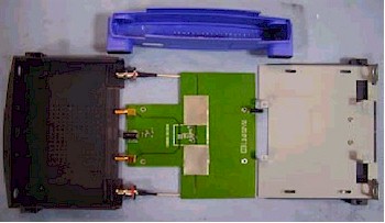
Figure 2: WSB24 Internal view
The pictures, which were also taken from the FCCID filing's detail documents, show that all the WSB24's circuitry is located under the metal shields that you see at the center of the board in Figure 2. Figure 3 shows a closer view of the circuitry, with the shields removed.
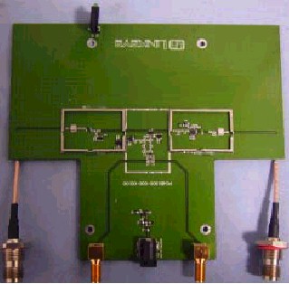
Figure 3: WSB24 circuitry
As you can see, the circuitry doesn't require very much space, due to both the integration of all the components, and the fact that smaller is better when dealing with gigahertz frequencies. The weight, by the way, is from the metal mounting plate at the right side of Figure 1, which gives the box some heft and resistance to being dragged around by the weight of its cables.